

Case study · Fluid dynamics & phase behavior
Frost-free microfluidic visualization: a 1000 bar, -70°C cryogenic test cell
For a leading research center in the energy sector, IRIAN Mecatronics designed and built a test rig to visualize microfluidic flows at 1000 bar (14,500 psi) and -70°C (-94°F). The custom equipment solves the key challenge of optical observation under cryogenic high-pressure conditions by preventing frost formation on the viewport.
01 — The research question
How can you visualize and characterize microfluidic flow under cryogenic high-pressure conditions?
Studying the phase behavior of fluids under extreme conditions is essential for validating models and developing new technologies in the energy, chemical, and geoscience sectors. This often requires reproducing combinations of pressure and temperature in the lab that are beyond the capabilities of standard equipment.
In this project, the goal was to simulate deep reservoir conditions at a micro-scale: injecting a fluid at up to 1000 bar (14,500 psi) into a microfluidic chip, cooling it to -70°C (-94°F), and directly observing crystallization or phase change phenomena. No off-the-shelf laboratory equipment combines such high pressure, localized cryogenic cooling, and clear optical visualization. Standard cryogenic systems cannot withstand the pressure, and high-pressure systems do not prevent the frost formation that makes observation impossible.
Maintaining a clear, frost-free optical view of a microfluidic chip at -70°C (-94°F) while it is subjected to an internal pressure of 1000 bar (14,500 psi).
02 — Our approach
The design process: from problem to solution
Our engineering team analyzed the project's three main challenges to design an integrated and reliable solution. Each technical decision was driven by the physical constraints and the client's observation goals.
-
Localized, vibration-free cooling
Achieving a stable -70°C (-94°F) over a very small area is a challenge. We selected a solid-state thermoelectric cooling system, applied directly to the sample holder. Unlike liquid nitrogen or mechanical chiller systems, this solution is compact, responsive, and generates no vibrations that could disturb optical measurements or microfluidic flow.
-
Ensuring frost-free observation
At -70°C (-94°F), ambient moisture instantly freezes on the viewing window, making it opaque. To ensure continuous observation, the microfluidic chip and the viewport are isolated in a sealed chamber, which is kept under a slight positive pressure with dry gas. This solution is more reliable than a simple purge and ensures a perfectly clear viewing window, similar to our modular HP sapphire reactor.
-
Sealing at 1000 bar and -70°C
Ensuring a seal at 1000 bar (14,500 psi) requires materials and fittings that can withstand thermal shock and temperatures of -70°C (-94°F) without becoming brittle. We selected standard, field-proven materials and connection technology for these conditions, avoiding the development of proprietary fittings. This provides the client with maximum safety and flexible connection to their upstream equipment, a principle we apply to all our custom HPHT reactors and cells.
03 — Beyond this project
Does your project have similar requirements?
Pharmaceuticals / Biochemistry
To study the crystallization of active ingredients, the principle of localized cooling and frost-free visualization is directly transferable. Wetted materials would be selected for biocompatibility (e.g., Hastelloy, PEEK) and the pressure ranges adjusted as needed.
Materials Science
Observing phase transitions in polymers can benefit from the same precise thermal control in a controlled environment. The sample holder geometry and the integration of additional sensors (e.g., stress, optical) would be adapted to the specific measurements required.
Aerospace
For testing fluids (fuels, lubricants) under cryogenic conditions, the combination of high pressure/low temperature and the robust design are key assets. The flow path would be adapted for specific flow rates and measurements (e.g., viscosity, cloud point).
04 — Specifications
The values for this project. Every system is custom-built, so they adapt to your requirements.
Show specifications · 1000 bar (14,500 psi) · -70°C (-94°F) · 30 x 20 x 1.175 mm
| Maximum injection pressure | 1000 bar (14,500 psi) |
|---|---|
| Minimum operating temperature | -70°C (-94°F) |
| Compatible microfluidic chip dimensions | 30 x 20 x 1.175 mm |
| High-pressure connections | 4 x 1/16" VALCO ports |
| Inerting chamber operating pressure | 0.2 bar (3 psi) max |
| Temperature instrumentation | 2 x PT1000 probes |
IRIAN Mecatronics designs and builds custom high-pressure, high-temperature equipment for research laboratories, technical centres and industry.
About the companyThey trust us






















05 — FAQ
Frequently asked questions
Can this HP cryogenic cell be used with corrosive fluids like H2S?
Yes, the design principle remains the same. To ensure compatibility with corrosive fluids, our engineering team would select appropriate wetted materials, such as Hastelloy C-276 or Inconel, instead of stainless steel. The design would then be reviewed to ensure compliance with the Pressure Equipment Directive (PED) using these new materials.
Is it possible to reach lower temperatures, such as -150°C, with this type of rig?
Thermoelectric cooling is optimal for this temperature range (-70°C / -94°F) because it is precise and vibration-free. To reach significantly lower temperatures like -150°C (-238°F), this technology is no longer the most suitable. We would instead opt for a liquid nitrogen circulation cooling system, which would require design changes to manage the cryogen and the overall footprint.
Can this system be adapted for samples larger than a microfluidic chip?
Yes, the principle of an isolated and inerted observation chamber to prevent frost is fully transferable. The main adaptation would involve the cooling system. Thermoelectric technology is effective for small surfaces; for a larger sample, we could integrate a fluid circulation cooling loop or another system to ensure temperature uniformity.
How are the pressure and temperature cycles automated on this equipment?
The equipment is controlled by a software interface developed by our automation engineering team. It allows users to program complex test sequences with pressure and temperature ramps and holds, while ensuring system safety. These cycles are fully validated with the client during the Factory Acceptance Test (FAT) before delivery.
Is your experiment limited by condensation or frost under extreme conditions?
Describe your pressure, temperature, and visualization requirements. Our engineering team will analyze your project's feasibility and get back to you with a custom solution proposal.
Related projects
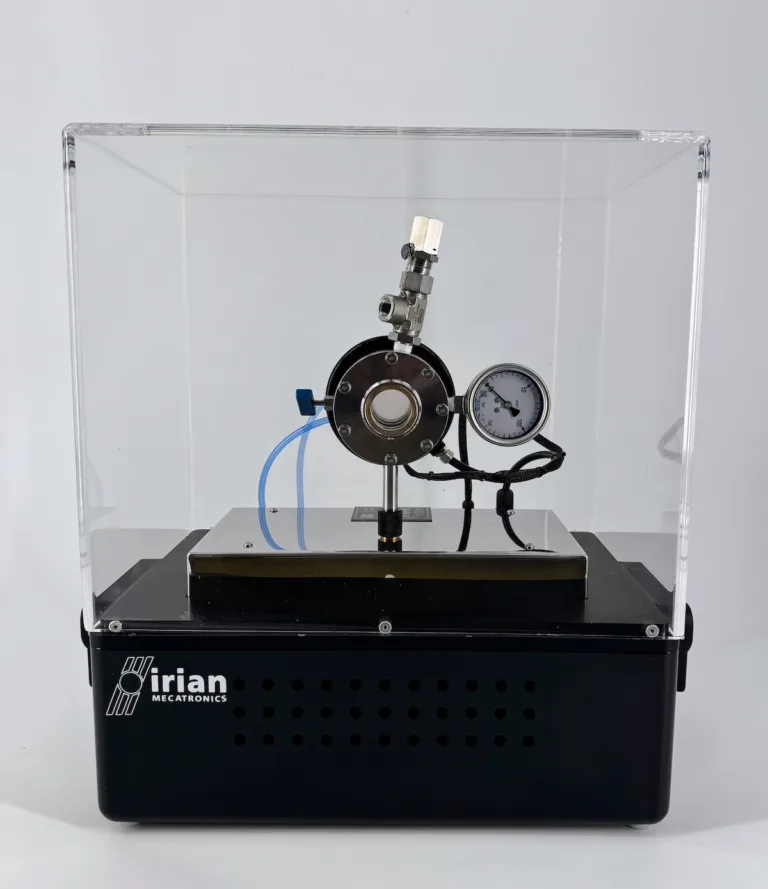 Fluid dynamics & phase behavior
Supercritical CO2 demonstration cell
Fluid dynamics & phase behavior
Supercritical CO2 demonstration cell
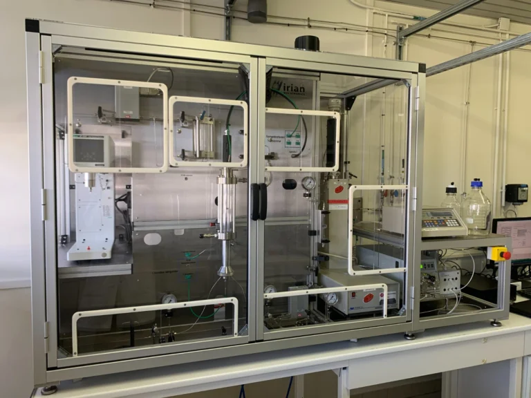 Fluid dynamics & phase behavior
Custom 120 bar sapphire column for gas hydrate research
Fluid dynamics & phase behavior
Custom 120 bar sapphire column for gas hydrate research
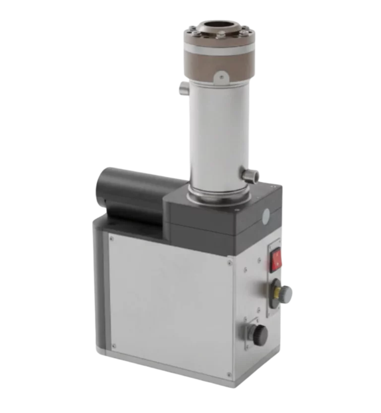 Fluid dynamics & phase behavior
500 bar / 150°C titanium variable volume cell for HP fluid research
Fluid dynamics & phase behavior
500 bar / 150°C titanium variable volume cell for HP fluid research
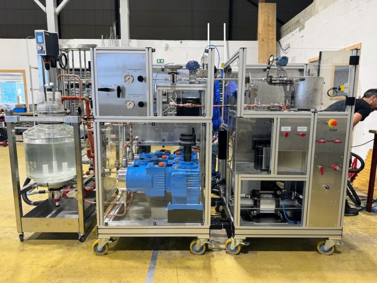 Fluid dynamics & phase behavior
HPHT pilot unit for simulating turbulent flow with DRA agents
Fluid dynamics & phase behavior
HPHT pilot unit for simulating turbulent flow with DRA agents