Skip to content

Observing phenomena under pressure

High-pressure visualization

For researchers and engineers studying phase changes, fluid flow, or material mechanics, observing a phenomenon under pressure is often the main experimental challenge. We design and build custom equipment—windowed cells, sapphire columns, microfluidic test benches—that provides direct optical access to the experiment, even under extreme conditions.

01 — The problems we solve

Your tests, our visualization solutions

Every experiment has its own visualization challenge. Here is how we have solved specific visualization challenges.

Comparing multiple flow regimes in a single instrument

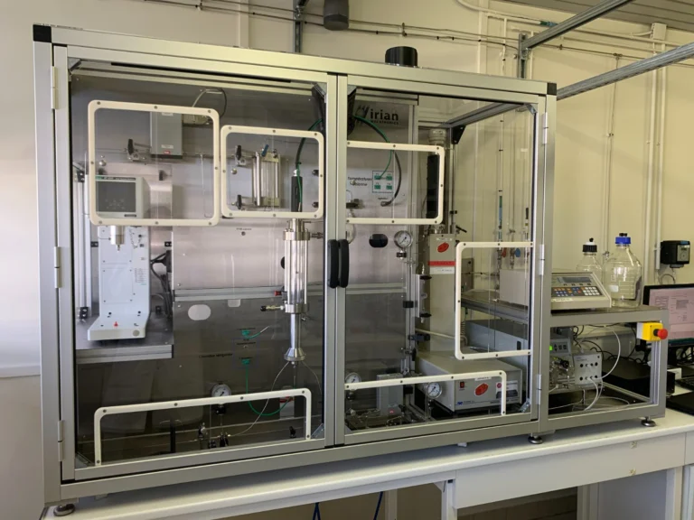
Comparing flows under static, stirred, or porous media conditions often requires several different instruments. The challenge is to design a modular vessel that can switch between configurations while maintaining its pressure rating, sealing, and the quality of the visualization.

Delivered for

See the project ↓

Demonstrating a high-pressure phenomenon safely

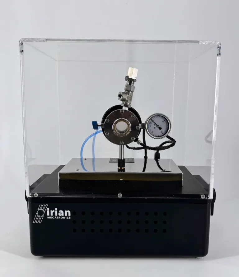
Presenting a phenomenon like a supercritical transition to a non-specialist audience requires absolute safety measures. The equipment must be portable, self-contained, and designed with redundant safety features that make it safe to operate outside a controlled laboratory environment.

Delivered for

See the project ↓

02 — Custom-built

Custom design for visualization

When a standard instrument does not provide the required observation, we design a solution tailored to the test constraints and measurement objectives.

Sapphire window cells and columns

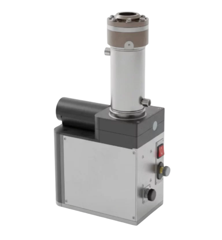
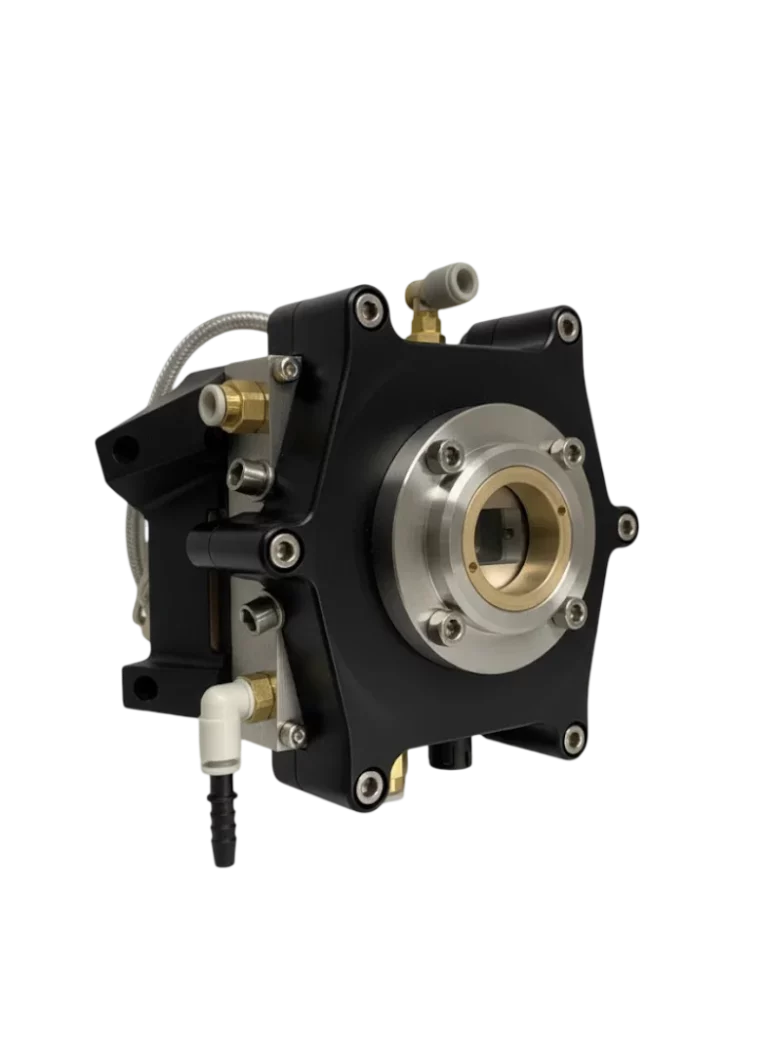
Designed to observe a phenomenon in a given volume when standard solutions do not meet the pressure, temperature, materials, or stirring requirements of the experiment. The design is adapted to each specific need.

Customization of volume, pressure, temperature, body material, and type of agitation.

X-ray transparent cells

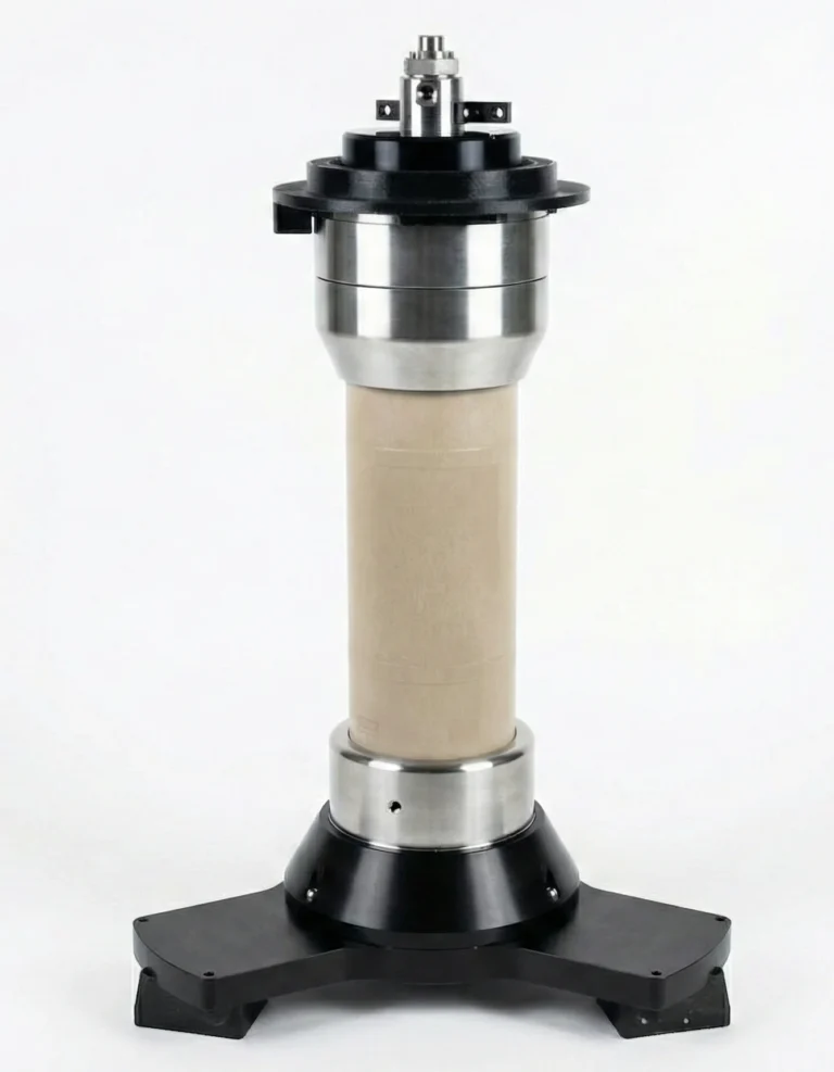
Developed for 3D tomography of a sample under stress. The design is adapted when existing cells are not compatible with the test constraints (pressure, temperature, chemistry) or the tomograph's geometry.

Customization of materials, applied stresses (axial, confining), and compatibility with the tomograph.

High-pressure microfluidic test benches

Used to visualize flow at the pore scale under extreme conditions. We develop solutions when standard systems cannot combine very high pressure with cryogenic conditions or lack the necessary optical access.

Customization of pressure, low temperature, and optical access (frost prevention).

03 — Measurements

Measurements enabled by optical access

Direct observation makes it possible to quantify phenomena that would remain invisible to conventional sensors.

Images and videos

Recording images and videos enables qualitative and quantitative analysis of phenomena. It is possible to study their dynamics and morphology or to measure flow and propagation velocities.

Phase transition points

Visual observation is the most reliable method for determining the exact conditions (pressure, temperature) at which a new phase appears: bubble, dew, crystallization, or hydrate formation.

3D tomography

This imaging technique reconstructs the 3D internal structure of a sample (pore network, cracks). Applying it in-situ makes it possible to track the evolution of this structure under mechanical stress or fluid flow.

Pressure, temperature, volume

Combined with visual observation, the precise measurement of thermodynamic parameters makes it possible to quantify the exact conditions under which the observed phenomenon occurs and to validate models.

05 — Our approach

Our approach: from scientific question to instrument

Each visualization instrument is the result of a rigorous analysis of the scientific objective and the experimental barriers to overcome.

  1. Analyzing the phenomenon to be studied

    Our engineering team starts with the scientific question: what does the researcher need to see? This could be a phase change, the propagation of a crack in a material, a two-phase flow, or the formation of crystals.

  2. Identifying the experimental difficulty

    We then identify what makes the observation difficult: pressure, temperature, material opacity, the small size of the object, the corrosive nature of the fluids... This is the technological barrier that the instrument's design must overcome.

  3. Designing the technical solution

    The technical solution is designed to specifically address the identified difficulty: a sapphire window for pressure, a PEEK cell for X-ray transparency, an anti-frost system for cryogenics, or high-grade alloys for corrosion.

Our visualization instruments are often at the core of test benches for fluid dynamics, geoscience, or extreme environment simulation. They take the form of specific reactors and analysis cells.

They trust us

  • CNRS
  • CEA
  • BRGM
  • Ifremer
  • EDF
  • TotalEnergies
  • Michelin
  • CETIM
  • Centrale Lille
  • Université de Pau et des Pays de l'Adour
  • Sonatrach
  • Saudi Aramco
  • Nanchang University
  • Adisseo
  • Lafarge
  • MDS
  • MIO – Mediterranean Institute of Oceanography
  • IRT Saint Exupéry
  • IRD – French National Research Institute for Sustainable Development
  • Groupe INSA
  • Aix-Marseille Université

06 — FAQ

Frequently asked questions

What is the maximum pressure a sapphire window can withstand?

There is no catalog limit, as the pressure rating depends on the entire assembly. The design of the window (thickness, diameter) and its support is calculated by our engineering team specifically for your test's pressure and temperature conditions, applying regulatory safety factors. One project, for example, enabled observation at 1,000 bar (14,500 psi).

How do you ensure the seal of a window under high pressure and temperature?

The seal relies on a mechanical design that protects the sapphire from excessive stress and on the choice of a sealing system (metal or polymer seal) suited to the test conditions (temperature, fluid type). Each assembly undergoes finite element analysis (FEA) to validate its integrity and sealing across the entire operating range.

Can these cells be used with corrosive fluids like H2S or brines?

Yes, the design is adapted to the nature of the test fluids. The cell body and wetted parts are manufactured from compatible materials, such as titanium, Hastelloy, or PEEK, to resist corrosion. Sapphire itself is a very chemically inert material, compatible with a wide range of substances.

Is your tomography cell compatible with my equipment (laboratory tomograph, synchrotron beamline)?

Yes, compatibility with the analysis environment is a key design criterion. We adapt the cell's external dimensions, its mounting interfaces, and the clearance for the X-ray beam to the geometry of your tomograph or synchrotron beamline. Fluid and sensor ports are also positioned so they do not interfere with data acquisition.

Do you need to observe a phenomenon under conditions that make it invisible?

Describe your experiment, the operating conditions, and what you need to measure. Our engineering team will analyze the feasibility of a custom visualization solution.

Discuss your project