

Case study · Geoscience & subsurface studies
Visualizing 3D rock deformation under stress: An X-ray transparent test cell
For a French national geological survey, IRIAN Mecatronics designed and built a custom test cell to visualize the internal deformation of rock samples in 3D and in real time. The equipment simulates deep geological conditions (20 MPa, 150°C) while remaining transparent to X-rays for non-destructive tomographic analysis.
01 — The research question
How to observe the 3D microstructure of a material under stress without destroying it?
Characterizing how materials behave under thermo-mechanical stress often requires multiple destructive tests to reconstruct a sequence of events after the fact. Ideally, phenomena like micro-cracking or fluid flow could be observed continuously, inside the sample, as conditions are applied. This is the goal of in-situ 3D imaging, an approach that opens new research avenues in geoscience and subsurface studies.
In this project, the goal was to visualize the internal deformations of a rock subjected to the pressure and temperature of deep geological reservoirs using X-ray tomography. Standard equipment faces a physical contradiction here: the metal cells capable of holding high pressure and temperature are inherently opaque to X-rays, making direct observation impossible.
To design a pressure vessel that can contain high pressure and temperature while being transparent enough to X-rays to allow 3D tomographic analysis of the sample inside.
02 — Our approach
Our design approach
To overcome this challenge, our engineering team (mechanical, instrumentation, automation) solved four interdependent technical problems, from material selection to sensor integration.
-
Balancing mechanical strength and X-ray transparency
The difficulty was finding a material that could withstand 20 MPa (2,900 psi) and 150°C (302°F) while being nearly transparent to X-rays—two properties that are usually mutually exclusive. We selected a composite material for the cell body, which combines the strength of high-performance fibers with the low X-ray attenuation of a polymer matrix. This allows the user to obtain high-quality 3D images without interrupting the test.
-
Maximizing the observation window without mechanical compromise
The metal end caps and pistons had to integrate fluid circuits and heating, but their mass could cast a shadow on the image. The solution was to use a high-specific-strength alloy to minimize their volume. Unlike standard steels, this design maximizes the area of the sample visible to the tomograph, enabling a more complete analysis.
-
Instrumenting the sample without leaks or image artifacts
Running sensor cables (for pore pressure and temperature) through the vessel wall at 20 MPa (2,900 psi) without leaks or metallic artifacts on the image was a critical issue. We developed custom-made, sealed feedthroughs designed for a minimal radiographic signature. This allows the user to correlate reliable physical measurements with real-time 3D imaging.
-
Heating the sample uniformly in a compact space
The system needed to reach 150°C (302°F) uniformly within a confined volume, without interfering with the equipment's 360° rotation. Instead of external heating with high thermal inertia, we integrated the heat sources directly into the metal parts in contact with the sample. The user benefits from rapid temperature ramp-up and precise control, ensuring the validity of the test conditions.
03 — The outcome
What this equipment made possible
The equipment makes it possible to directly correlate a material's mechanical properties with changes in its 3D microstructure, opening new perspectives for research in geosciences.
Does your project face a similar challenge?
Materials science (aerospace, automotive)
A common challenge is the in-situ study of micro-crack formation in a composite or alloy under stress. The principle of an X-ray transparent vessel, pressure and temperature control, and non-destructive 3D analysis would remain the same.
Energy (hydrogen storage, batteries, CCUS)
The goal is to visualize phase changes or swelling in storage materials during cycles under pressure and temperature. The need to contain a gas, control temperature, and perform 3D imaging during operation, as in our custom CCUS reactors, is a shared requirement.
Biomedical / Tissue engineering
This involves observing the growth of synthetic tissue or the degradation of an implant in a bioreactor simulating physiological conditions. Non-destructive 3D analysis over time, temperature control, and fluid management are directly transferable principles.
04 — Specifications
The values for this project. Every system is custom-built, so they adapt to your requirements.
Show specifications · Up to 20 MPa (2,900 psi), hydrostatic · Up to 150°C (302°F) · In-situ 3D X-ray tomography
| Confining pressure | Up to 20 MPa (2,900 psi), hydrostatic |
|---|---|
| Sample temperature | Up to 150°C (302°F) |
| Compatible analysis technique | In-situ 3D X-ray tomography |
| Internal instrumentation | Pore pressure and temperature sensors close to the sample |
IRIAN Mecatronics designs and builds custom high-pressure, high-temperature equipment for research laboratories, technical centres and industry.
About the companyThey trust us






















05 — FAQ
Frequently asked questions
Can this tomography cell be used with corrosive fluids like H2S or brine?
Yes, the design principle is fully adaptable to corrosive fluids. The main change would be the choice of materials for all wetted parts (pistons, circuits, sensors). We would select specific alloys like Hastelloy or Inconel, as we do for our corrosion test reactors. The composite body already has excellent chemical resistance. The process remains the same: stress analysis, material selection, and qualification.
Is it possible to design an X-ray transparent cell for much higher pressures, above 100 MPa?
Reaching very high pressures while maintaining a large viewing window is a major challenge. The all-composite body approach has its limits. For pressures around 100 MPa (14,500 psi) and higher, a different design would be considered: a high-strength metal cell (steel, titanium) equipped with dedicated windows made of very hard, X-ray transparent materials (diamond, sapphire). The choice is a trade-off between maximum pressure, the size of the observation area, and the budget.
Our tomograph has a very limited workspace. How can you ensure the equipment will fit?
Integrating equipment into an existing environment is a constraint we manage on every project. Our engineering team works from the drawings and 3D models of your tomograph to design custom equipment that strictly respects the available space, mounting interfaces, and the clearances required for rotation. The choice of high-specific-strength materials, as on this project, directly contributes to the system's compactness.
Can the equipment apply other mechanical stresses, like in a triaxial test, during tomography?
Yes, the principle of an X-ray transparent cell can be extended to include complex mechanical loading. We can design versions that apply a deviatoric stress to perform a complete HPHT triaxial test under tomographic observation. This requires a specific design for the pistons and loading system, but the basic philosophy (confinement, P/T control, X-ray visibility) remains the same.
Is your experiment stalled because you can't see what's happening inside your sample?
Describe your high-pressure, high-temperature observation challenge. Our engineering team will analyze your project's feasibility and get back to you with a technical proposal.
Related projects
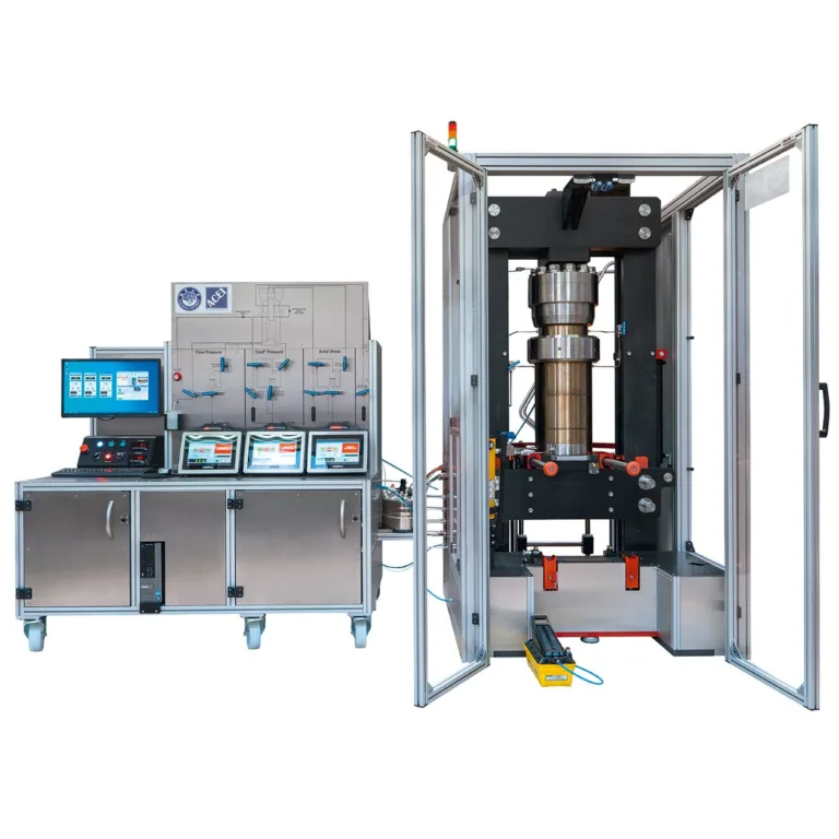 Geoscience & subsurface studies
Custom HPHT triaxial testing press for geomechanics research
Geoscience & subsurface studies
Custom HPHT triaxial testing press for geomechanics research
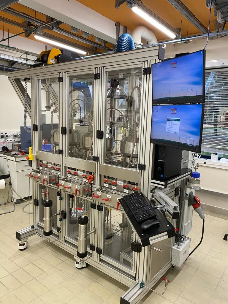 Geoscience & subsurface studies
Multi-cell 400 bar / 250°C test bench for formation damage analysis
Geoscience & subsurface studies
Multi-cell 400 bar / 250°C test bench for formation damage analysis
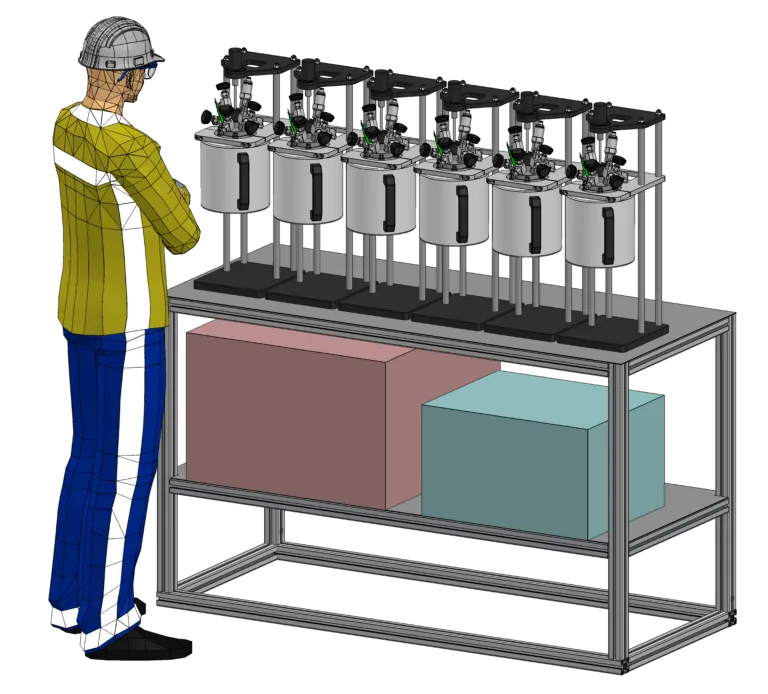 Geoscience & subsurface studies
Custom Hastelloy C276 HPHT reactor system for geoscience research
Geoscience & subsurface studies
Custom Hastelloy C276 HPHT reactor system for geoscience research
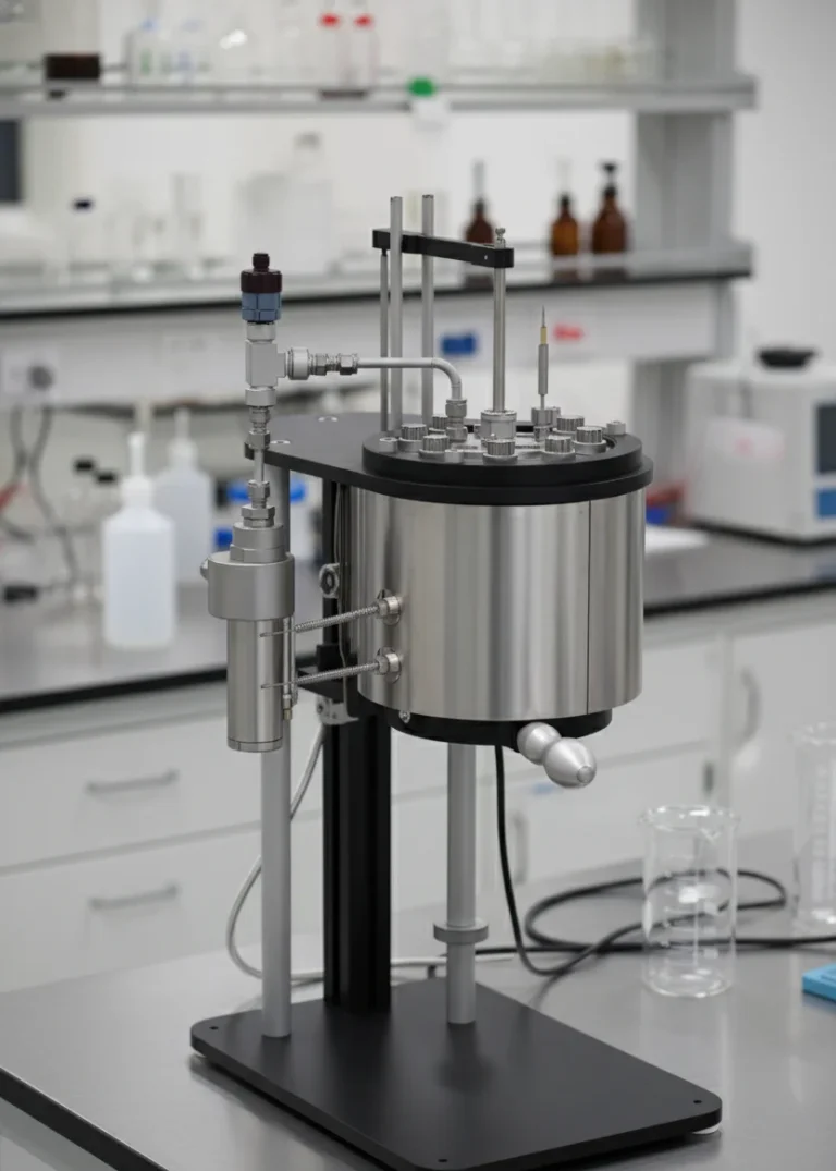 Geoscience & subsurface studies
Multi-mode HPHT reactor for geochemical simulation in corrosive media
Geoscience & subsurface studies
Multi-mode HPHT reactor for geochemical simulation in corrosive media